
Recently I asked a question on StackExchange about what happens when 2 voltage signals are tied together. What’s the resultant voltage and what decides this voltage? The whole train of thought started when I was trying to contemplate what happens when you use pull-ups on signals that are not Open Drain.
I create and simulated a Circuit with the same scenario in LTSpice. “V” is the voltage between the “+” terminals of V1 and V2 and its shown on the right of the simulation. We will confirm the simulation result by doing some math later.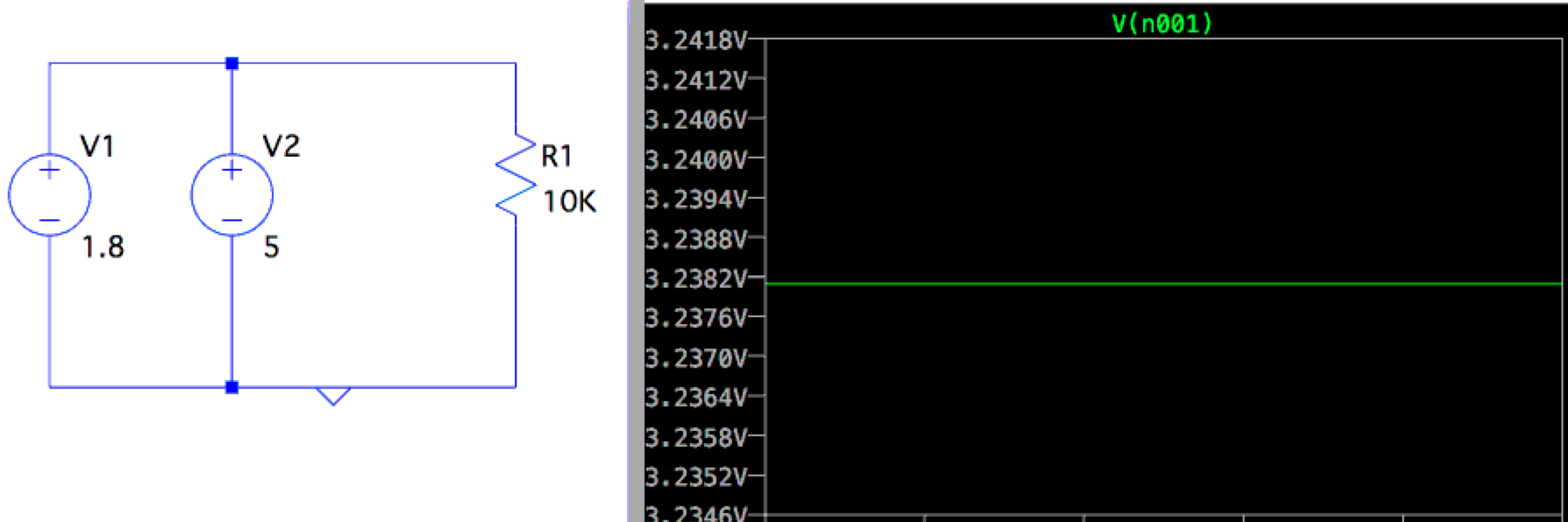
The question is what is the voltage across the load after hooking them up together. And what do the currents look like? Is there a current flowing between the 2 sources as well (apart from the current flowing to the load) because 5v > 1.8v? The simulator refuses to do a simulation without your author adding an internal resistance to the voltage sources first. All voltages sources have certain internal resistances, so that’s fair. This can be considered analogous to having a voltage signal with a certain resistance along its path which limits its current sourcing (or sinking) capabilities.
So I added 1k resistances internally, normally the resistance of a voltage source is far less than this. AA batteries have just 0.1-0.2ohms.
Now the circuit looks something like this: 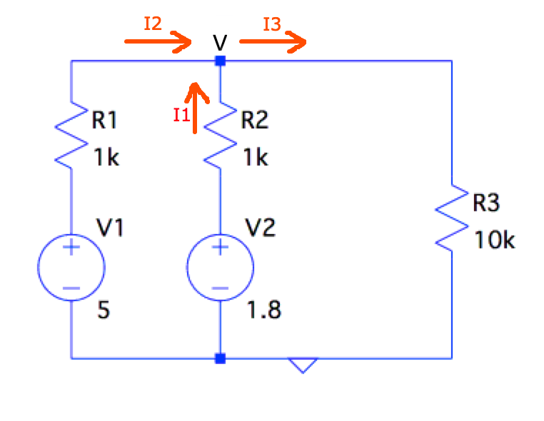
One can simply apply Kirchoff’s current law to the above circuit, the direction of currents would be as in the circuit. I1 and I2 are the currents flowing through R2 and R1 respectively.
By Kirchoff’s law, All the current entering the node labeled V will be equal to the current exiting it even if the currents are not in the actual direction shown above. From this we see:
I1 = (1.8 - V) / 1k
I2 = (5 - V)   / 1k
I3 = (V - 0)   / 10k

I3 = I2 + I1
V / 10k  = ((1.8 - V) / 1k) + ((5 - V) / 1k)
V = 3.2381v
Fom this we see the voltage at V is somewhere between 5 and 1.8v. Infact, where it is between 5 and 1.8 depends on how strong or weak the resistances associated with the sources are. If the resistances are lower, then the sources have more of an influence and vice versa. An interesting observation is I1 is negative if you plug V=3.2v in the above equation. This means the current for voltage source V2 (the 1.8v voltage source) is actually flowing into it rather than out of it (its being sinked) and so I1 is actually opposite in direction to the picture shown above.
A simpler case is having 2 voltage sources of the exact same voltage values, in this case the circuit would look like: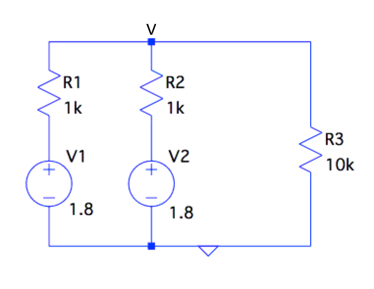
Thevenin’s theorem provides an easy simplication into the following, where the equivalent voltage source value is the same but the series resistance is now halved. This results in the following circuit:
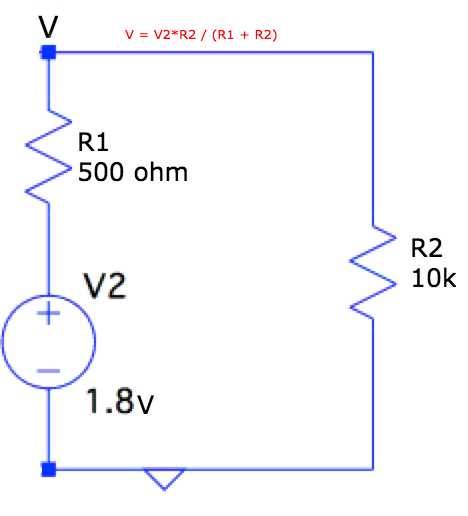
Now you can use the Voltage divider concept and easily solve this:
V = V2 * (R2 / (R1 + R2) )
  = 1.8v * ( 10k / (10k + 0.5k) )
  = 1.7142v
As you would notice, the 1k resistance dropped around 0.085v of voltage before getting to the 10k load. Thanks for reading. Please leave your comments or inputs below.